Tascam 38 No sound in Sync Mode!

The important thing is to know how the unit behaved before the P/S upgrade. If there were problems then it was imperative to have found them first.

Upgrading capacitors is very straight forward. It does not affect performance unless a cap is in backwards!

By indicating a changed fuse and it blowing tells me there was something else going on.

I would also not change wiring on boards.

What is the S/N of your unit?

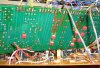
Have you removed all the sound cards and tried measuring voltages at the P/S M-B connector?

I have attached my chart of wire colors and voltage readings for that plug. I use paper clips to push into the connector but very carefully so they don't short.
 

Attachments

  • Tascam 38 M-B Pin Voltages.pdf
    127.8 KB · Views: 15
Thanks, I'll check it out, but I'm still afraid to blow out other stuff when powering on. I'll try to disconnect everything that goes to the control board.

About bypassing caps, you just have to put the WIMA parallel with the capacitor you want to bypass? That's what I've always known. Otherwise that could be the problem...

The wires that I switched were definitely wired wrong, so these are right now.
 
The .01 WIMA by-pass caps go across the + and - terminals of the large caps on the foil side of the board

See the attached photo of a 38 P/S board. (I made it a bit smaller so better visible w/o overlays from site)

How could those wires be misplaced? Are you sure of this?

is your 38 S/N 400000 or higher?
 

Attachments

  • Tascam 38 P S mod.jpg
    Tascam 38 P S mod.jpg
    117.7 KB · Views: 19
Didn't you desolder all the connections to get the PSU out of the case?
Thanks for the pic, that's a great help. I think I got it. If you check the brown cable, it goes to 24, the gray one (left to it) to 23 and the blue to 22. I've written all the connections down when desoldering and made a fault there. I've written down 22-gray, 23-brown and 24 blue. That's when the fuse blowed. Then I switched the brown with the blue (so 22-gray, 23-blue and 24-brown) and that sounds like a short-circuit (that explains the blow up of some of the NAND IC's). I'll solder everything back and see if I'm now right on this.

S/N is 135116

WIMA caps were placed correctly.
 
I do not remove the P/S board when updating. I do it with the board in place.

It gets a little tricky, but I am able to move the board around to get at all the caps.

Now I understand how your cables were reversed. This is why I do not remove the board during re-cap.

I thought you might have had a later version 38 which would have explained the wire color difference on 22, 23, & 24.

S/N 400000 and later has a different M-B and slight differences in a few other areas. Manuals for the earlier versions will not show the differences of the later versions.
 
There were some extra capacitors on de REC cards (C144-145), which were not shown on the schematic. Probably a revision.
 
Ok, I've done the rewiring, power it on and nothing happened. That's good I suppose ;-)
No fuses are blowing anymore, but I still have to change 3 7400 IC's. Now the capstan only works. I've ordered some and have them next week. I'll let you know if the machine is going to be up and running again after putting the IC's back in place.

Thanks a lot for your help - would be lost in the woods without you!
 
That's a good sign. Blowing IC's is not good. You may have damaged a few transistors near those IC's. You might want to check them ahead of time

It's a tough way to get a unit to work. I know it well. I have a 38 now in which I cannot get any audio to pass through. It is a huge challenge!

Frustrating work.

Always happy to help. I have learned from others as well.

Use the chart I attached and check P/S voltages at the M-B plug from P/S. make sure you have +15 & -15V. Very important.
 
These are the voltage readings:

9+11 = 14.88 V
10+11 = 15.11 V
2+8 = 24.2
1+2 = 8.11

This without removing the sound cards, but disconnecting the connector from the mother board. It's to much work to remove all the sound cards.
 
How can you check them? Because visually they look allright.

Thanks
 
You need a digital multimeter that offers the ability to test diodes, etc. , or you can get a meter such as this.

http://www.testequipmentdepot.com/elenc ... /dt100.htm

Attach the positive (red) multimeter probe to the transistor base lead;
Attach the negative (black) multimeter lead to the collector lead.
Read the multimeter display; it will give either a "pass" or "fail" indication.

Sometimes you can get numerical readings across the base and the collector. If no reading the part is usually bad.

NPN and PNP read differently. So sometimes you have to reverse meter leads to get a reading.

This is just a quick overview.
 
I have a multimeter that could do that. Cool, thanks!
 
Check every transistor on the large control board including the power units attached to the aluminum rail heatsink.

It will take a little time but you might find that some of the IC's you think are bad may not be.
 
All the transistors measured allright. I only found one attached to the frame.
 
Ok, got the 3 broken sn7400N back in, but when I connect the keyboard control and hit play nothing happens. :-( Not even the leds are working.

Do you still thinks other IC's could be damaged? Then I probably have to replace all of them and that will be loads of work and not speaking of cost...
 
Check every fuse again w/a meter to make sure they are OK. If the P/S is generating the voltages you stated then you know it is working.

I would make sure the other wires you removed from P/S are properly soldered.

I would have to look over the logic schematic again to see the path.
 

New threads

Members online

No members online now.