Tascam 52 help needed

TimR

New Member
Joined
Nov 19, 2018
Messages
12
Karma
0
Gear owned
Tascam 32, Tascam 52
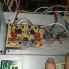
IMG_20181118_125825517.jpg I'm hoping someone could help me out. I have a Tascam 52. I have a paper manual for it however my deck has XLR connectors on the back, No volume pots on the front and my manual doesn't cover the In/Output board.
I picked this deck up from a recording studio and they hacked some things together, one was complete disconnection of the In/output board. This one in particular has a couple of variable pots on it which of course my manual doesn't have either.
So, I'm looking for information, a scanned sheet from the correct manual, or some pics if anybody has anything I would be grateful. I'm afraid the studio has damaged an op amp or replaced something with the wrong thing etc etc. I already repaired one of the channel boards and got the machine working for the most part but what happens now is when I connect the yellow wire (-15vdc) the playback gets muddy to the point of non recognition.
I did get some sheets from Sam but the board is different in a 52 NB or DB apparently.
 
Last edited:
Well Op amp circuits are really pretty simple to work with. Typically the signal comes in unbalanced then goes to a Op Amp first to cause an inverted signal. This inverted signal then goes to another Op amp that then buffers the signal for output and may add some gain to the output signal level to get it to +4dBu. The original signal also goes to a buffer amp. That is what the balanced system is- is two strong signals going the opposite direction in two pins.

I would flip the board over and knowing the voltage pins are usually 8 for positive and 4 for negative, check for all of those. Once that is confirmed then you can take some voltage measurements at the output to see if the Op amp is damaged. So pins 1 and pin 7 are outputs and with a dual polarity supply the output of these should be near 0 Vdc. If they are not that would indicate that one of the internal circuit is damaged. If there is a socket change it out. Don't just put Bi Fet Op Amps in without proper supply bypass.

Keep in mind people plug Phantom supplies with 48Vdc into these decks sometimes and 48Vdc is way too much for the op amp to handle which then damages them. If all output are at 0 Vdc then I would look at how they are wired to the XLP connection. If you see a certain op amp you can download the datasheet for it on the internet which will tell you it's characteristic. If they used some weird Op Amp in the deck then returning to what Tascam used in other unbalanced to balanced circuits would be a way to go.
Make sure the negative voltage line goes to the pin 4 of op amps otherwise it may be getting connected in the wrong place. This board can not be that hard to figure out. I might also add that those grey wires go somewhere and there should not me more wires on those connectors than from the converter- what are those?
 
  • Like
Reactions: TimR
The grey wires with the blue bands go down to the RCA connectors on the back of the motherboard.
My main hangup is this. Since the op amps are already socketed, makes me think these guys did some goofy stuff here already. I wish I had the original parts list for that board. I would love to put in what Tascam designed, or maybe those are original. I do know this. On the playback and record boards there was at least one op amp blown out> I went ahead and replaced them and got the board functional but I really don't know what blew them out originally, maybe it was this baord.
Anyways, I can do as you suggested I just don't want to blow it out again.
The tech did leave a scrap of paper inside the deck of where the wires connected to the XLRs so I'm pretty confident about how I put those back on anyways....
 
My concern of the grey wires are they are tapped into the XLR output and that is not how they are suppose to be. What TI op amps did they put in?
 
  • Like
Reactions: TimR
All 3 are TL072CP. The 2 side by side are identical in appearance and the one by itself looks to be a different run for lack of a better word. I may be way off with my gut feeling but...
 
I think in the Tascam 58OB I just worked on has NJM2041 op amps which are better specs than the TL072. But that is all in the area where you probably won't hear the difference. The NJM2041 have 25mA drive current.
 
  • Like
Reactions: TimR
I ordered 4 OP amps from Mouser, probably be in next week. I'll keep you posted.
and Thanks Again !
 
OK, I have a lot of Op Amps here and in some cases I have to order a particular part as well. There are so many models of parts out there. People go crazy changing parts around when there is relatively no difference in this application. Just remember to plug them in the right way the first time as backwards destroys the Op Amp. If looking at a IC from the top there should be a cut out at the end of the pin one and the pin one is in the lower left which pin 8 is upper left.
 
Yes, a lot of people think they know better than the engineers that designed it. It's rough getting a piece in that has been doctored by a self proclaimed sound engineer/electrical tech. I'll make sure to get them in properly. There are sockets in there already but I will double check those as well. They had a 50/50 shot at getting them in right and I don't need to go down broken path.
=)
Happy T-Day ! ! !
 
Even if the sockets could be in backwards you can always tell which way they go in with a meter by measuring the pin 8 for a plus value voltage and pin 4 for the ground or negative voltage. Then from that you can be sure or correct socket installation. Anyone who puts an IC socket in and has soldering skills should know how to put sockets in properly. Check for bad soldering as the bridging of pins of parts can be the cause of malfunctions. I have seen this even from Technicians when they are in too much a rush. They also miss broken solder joints.
 
  • Like
Reactions: TimR
ok, Here's where I'm at.
All 3 op amps AND Sockets replaced with same type TL072CP, Problem remains, both channels sound lke the signal is going thru a sock drawer.
Replaced all electrolytics on that board, problem remains, all except one cap was within tolerance.

Here are all the voltages taken.

OP #1 inputs come here first thru those orange film caps.
1-.013 8-+15.00
2-.343 7-.009
3-.007 6-.359
4--15.05 5-.005


OP #2 (top left)
1-.007 8-+15.00
2-.004 7-.002
3-.002 6-.004
4--15.05 5-.002


OP#3
1-.012 8-+15.00
2-.005 7-.007
3-.002 6-.002
4--15.05 5-.002

all measurements taken VDC while passing signal.
So, at this point I'm interested in the wiring for the XLR's. one pin has what looks like a chassis ground wire daisy chained, then there's the shield and a signal wire going to the other 2 pins like in the first posted picture with the In/output board doubled up on it.IMG_20181129_213013864[1].jpg
This is the note that I found in the machine from the tech. This is how it's currently wired.

I dunno, let me know what you think or if there's something else on the board itself I can test. I'm stuck
 
Last edited:
Here is a pic of the inputs. I noticed that there is a bare metal jumper from the black wire to the green (right) and also on the orange (left) again to the daisy chained black wire.IMG_20181129_214716388[1].jpg
 
You may be dealing with a butchered wiring job. Why not just return everything according to the schematic. XLR connectors are Pin 1 always ground. Pin 2 or 3 can be positive and then the opposite the negative. Positive and Negative is in relation of the phase of a sine wave as viewed with a scope. Positive will be positive deflection while the negative will be negative deflection phase wise- this can be viewed with a dual trace oscilloscope. Currently the pin 2 being positive is the standard for equipment but some Microphone connectors are positive on 3. This is what happens when the industry does not standardize early on with regard to wiring connectors.

If you put the same 1KHz sine wave into the deck and scope the output of the pins the amplitudes and phases should be consistent between the two connectors. Recovering equipment from butchers is not always easy to do if you are not a seasoned Technician. You can do it though.
 
  • Like
Reactions: TimR
This is my goal to return this machine to the state it belongs in, However, This is the only part my manual doesn't cover. I was originally hoping for a scan from a book that covers this but seems to be a rare find. I have asked a few sellers on ebay to see if their books cover this machine with XLR's but no luck so far.
I will do as you suggested and see if there is something simply reversed and let you know what I find, if anything.
I appreciate your time and knowledge on this deck for sure.
 
Looking at that last picture, does that jumper from the ground to one of the signal wires look right? That would mean tying one of the signal wires to ground on the input side which doesn't make sense to me but these commercial decks I don't run across often at all. I have done a considerable amount of consumer decks but something of this magnitude is a new challenge for me.
Please let me know what you think about that jumper. This weekend I'll run a signal thru and follow it with my scope.
 
I am not sure this will help but if one looks at circuits of other decks that provide the same function such as the BR20 then it might be possible to determine what they are doing in one model to apply the same idea to the model you have. In the attached document they used NE5532D Op Amps without the transistor buffer amps as is done in some other decks.
It may be of help. The top schemo is for Time code but will also apply, the lower is the audio connector 1/2.
A jumper to any signal pin from ground is totally wrong and may be part of the issue. They do this to unbalance the output so as to feed unbalanced transformer inputs. It should have been done at the input of the other equipment not here.
 

Attachments

  • Br-20_smBal Out.pdf
    270.8 KB · Views: 2
  • BR20 Bal out pg66.pdf
    218.2 KB · Views: 3
Last edited:
  • Like
Reactions: TimR
After the education, THIS makes more sense and should look better to you, after all it works now. (Yesss!)IMG_20181201_073131370.jpg
Now i just need to straighten out the remote wiring as they did similar stuff to it and find a replacement for the power mute relay. The coil is open for this and I'm having trouble finding another or a sub for it.
Any suggestions?
IMG_20181201_073816382.jpg
They hardwired the contacts when they figured out the relay no longer worked.
 
Last edited:
This is the typical result from people that do not belong in the machine. This is a rather old design type magnetic reed relay. I can not see from this picture if it is a Double pole or what in order to sub something in. Generally a DIP (Dual In line Package) relay of that voltage and contact type would be wired in using either standoffs to a proto board or relay wired with leads
then inserted to the correct PCB holes. The relay could be installed on an IC socket or wired directly. A study of the schematic would tell you what you need to do as far as function goes. I suspect the relay is NO (Normally Open) and closes once power supply becomes stable. A DPST or DPDT relay of the DIP type and 12 Vdc will do the job. Most Technicians have something in stock like that but a fast search on the Mouser Electronics site will return many options. This relay here is used in some other tape decks for the same function.
https://www.mouser.com/ProductDetail/Omron-Electronics/G5V-2-DC12?qs=sGAEpiMZZMs3UE%2bXNiFaVE2oOs0DTHVbJpO4d29eV%2bs=
Of course you can select what you want to put in- they are usually not very costly.

A similar part to these relays are used in other circuits for muting in the 40 and 50 series on the cards. They are however usually 24Vdc. This below is 12Vdc for this application.
https://www.digikey.com/product-det...lectronics/DIP12-1C90-51L/374-1294-ND/1975755

If you need more help I can assist.
Even a more pleasing price here-
http://www.mpja.com/12VDC-DPDT-DIP-Relay/productinfo/32559 RL/
or
http://www.mpja.com/12VDC-DPDT-DIP-Relay-Axicom/productinfo/32715+RL/
 
Last edited:
  • Like
Reactions: TimR
It just opens the signal wires from right and left on a power down. I did sub another relay I found locally, I was hoping for a "drop in" for a cleaner repair but currently I have a 12v double pole single throw in there with leads. It works but not as clean as I want. Oh well, thought i would ask.
Going to press on now with calibration to finish this guy up.
Thanks again Sam. you have been a big help.
=)

These look like the ones I've used on Tascam 32's I've done in the past,
https://www.digikey.com/product-det...lectronics/DIP12-1C90-51L/374-1294-ND/1975755

Love the drop in's
 
Last edited:
Finding old reed relays for drop in is not going to be easy. Yes you might find one or some at some surplus place but they are really not current technology and so I would opt for a DIP relay in a machine pin socket so if it was to go bad a change out would be easy.
These relays usually do not go bad and so I suspect it's failure has more to do with who was messing around with it.
 
  • Like
Reactions: TimR

New threads

Members online

No members online now.