DM4800 Phantom Power Kaput

Hi Dave, about your questions:
When the board is powered on and I have the mic/line input fader up, #16, I move the 48v phantom power switch off, on, off, on and I get signal bumps on the meter bridge for that input. This appears to be normal. Same result on every mic/line input with 48v power. If the Amp boards are not receiving 48v power, would I still get those signal bumps on the meter bridge?

Normal result because we switch the input load from ground to +48V. Even if +48V is missing, it creates a "pop", especially if +48V is open or show a different impedance than gnd.

If I plug in a run of the mill dynamic mic, (AKG D190ES) the channels all perform normally with good signal output. Does this indicate anything to you?

No, all seems OK on Input side ( except we have no phantom power...).

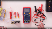
Need some measurement...

About DeoxIT, I use the products and are very efficient: Contact cleaner product or Fader Lub. It is a good idea to use it especilly when all is open and you can access to the board, fader or contact.
 
Morning Herve,
"Normal result because we switch the input load from ground to +48V. Even if +48V is missing, it creates a "pop", especially if +48V is open or show a different impedance than gnd".

Okay, this makes total sense to me. And this "pop" was the beginning symptom. I'd be sitting here at the board noodling around on the guitar and the channel would glitch or pop. Sometimes it would do this and other times it wouldn't. 48v power was on so it appears that it was either cycling off and on or the impedance was intermittent when this pop would happen.

Okay my friend, I'm gonna get the setup torn down and the board open when the multi-meter and cleaner shows up and start the search.

You've given me a really good road map and starting point for all of this Herve and I want you to know how much I appreciate you taking your time to help me with this. Once I get some measurements I'll report back with the results.
Thank you sir!!!
David
 
Hello Herve,
I have the multi meter now and I've done a few test. I unplugged the mic cable from the board and turned the board on. I then turned the 48v power on and took measurements at several of the XLR inputs on that Amp board. It's reading 48v or a little above. Turned the 48v power off, reconnected the mic cable, unplugged the mic, turned the 48v power back on and took measurements at the female end of the cable and again, 48v power is registering.
I am starting to suspect that it is my microphone that has bit the dust. If 48v registers at the inputs and registers at the end of the mic cable then it's got to be the mic. What do you think?
David
 
Hi Herve,
Another wrinkle in the mystery here and I think what you responded with below herein, lies the answer.

"Normal result because we switch the input load from ground to +48V. Even if +48V is missing, it creates a "pop", especially if +48V is open or show a different impedance than gnd".

Come to find out that this "popping" I mentioned above, I believe, damaged my AKG C414. I have a friend who lives just down the street from me and his son has a descent recording set up. I took the 414 down to their house and we plugged it into his system, applied 48v power and nothing. The 414 is dead. His son, gave me a mic he didn't want any longer, a Audio Technica AT 2035. Large diaphragm condenser mic. I came home and set it up and played through it a little while and for a $160.00 mic, this damn thing sounds good. BUT, the "popping" returned, intermittently. I think somewhere along the line and over time, this popping shorted out my 414.

I was partially happy because I was going to report back to you that it was the mic that was the problem and that I wasn't going to have to tear down the board but when I got the AT mic plugged in and played for awhile and the popping returned, it appears that I am going to have to open it up and see what's what. If the popping is being generated by a grounded input being switched to 48v power are we looking at the last part of your sentence above?
"especially if +48V is open or show a different impedance than gnd".

What would I check on the Amp board for that?
Thank you Herve!!
David
 
Hi, Good job Dave. Now we have to find the origin of the pops. Possible reason I have in mind:
1) 48V power supply "cut" some ms. (connection, switch, SW Power supply condensator failure.
2) Condensator failure at the input of the channel

IS this pop audible on all channel or one or some specific channel?
The answer give the reason 1 or 2

My approach is to do a test without mike:
Create a plug with a XLR male and 2,7K or 4,7K resistance between 2 and 3
Activate the Phantom power, connect the plug on the channel to test (CH 1)
Power on
hear the channel. If pop appends, repeat the test on other channel CH 5 . If appends will be a power supply problem.

Normally I will monitor the Phantom power supply with a Digital scope and will trigger if less than 47V and memorize the signal. Doing it this way, you can do other activities..

Waiting your answer to decide how to repair.
 
Morning Herve,
The aggravating thing about the "popping" is that it is intermittent. I played for a couple of hours yesterday feeling out the new mic I have and it never happened. Everything worked beautifully. Today? lol...............Who knows what today brings!!!

I can't say if the popping is happening on other channels so I'm going to play around with that today to see if it's occurring on other inputs. I'll check the same inputs on that particular Amp board and the other inputs on the other 2 boards. Hopefully the popping will happen when I'm doing this.

I want to understand what it is that your saying here so let me take a shot at what you suspect is happening.

1) 48V power supply "cut" some ms. (connection, switch, SW Power supply condensator failure.
The 48v power supply is basically cutting off and on for a millisecond or so. Hence the pop when it goes from being grounded to 48v. Like turning the 48v power switch off and on and getting the bump on the meter bridge like we discussed previously. Is this correct?
And the problem could be the connection itself, the 48v switch itself, the SW (Switched?) power supply condensator?
Is this correct?

2) Condensator failure at the input of the channel
So, there is this "condensator" thing on each channel input. Can I assume that it too, is on the Amp boards for the 4x4=8 inputs? Would you educate me on this condensator? What does it do?

The 4800 here in the US is 120v AC. So this voltage must not only be taken down to 48v but it must go through some kind of a "transformer rectifier" (TR's) to transform the AC power to DC phantom power. Is this what the "Condensator" does?

This is simular to the eletrical system on aircraft. I flew the DC9, B717 and B737 aircraft for decades. The electrical system of an aircraft is basically AC with components powered by DC ie.............ATC comm radios, VOR navigation, GPS navigation, ILS components. They're powered off 3 electrical busses, DC bus 1, DC Bus 2 and standby backup power from the 28v DC batteries if all that other stuff quits etc........The TR's transform AC to DC power.
Am I close?

Create a plug with a XLR male and 2,7K or 4,7K resistance between 2 and 3
Okay, bear with me here please. I'm totally lost on this one!!! :)

"Create a plug with a XLR male"
Do I take an XLR cord and severe the male plug off of it and expose the wiring for the pin wires on the back of it? Can a test XLR male plug be purchased to accomplish this testing?
and 2,7K or 4,7K resistance between 2 and 3
1. By what means do pins 2 and 3 get connected as this would have to be done outside of the XLR jack itself because it gets inserted into the input. Exposed wires on the cable? An adapter maybe?
2. What supplies the 2.7 or 4.7 resistance between pins 2 and 3 or do they short themselves out normally when connected?
3. If this is done by the exposed wires for the pins, how do I know what wire is what pin?


Once all this is accomplished, I plug the XLR jack into the board and turn the 48v power on and check the resistance between the pins. With the volt meter on the resistance setting?

Whew!!! I apologize for the million questions. The unpredictable variable with all of this is the intermententcy of the problem.

Okay professor, you're probably ready to throw me the hell out of your classroom because of the million and one questions here!!! But this is how I learn and you're surely educating me on all this Herve.
I'm thankful you are taking your time to do so!!!
Thanks fren!!!
 
Hi Dave, some answers about your questions:

First I miss translate "Condensateur" (in french). It is capacitor!!!

You wrote:
1) 48V power supply "cut" some ms. (connection, switch, SW Power supply capacitor failure.
The 48v power supply is basically cutting off and on for a millisecond or so. Hence the pop when it goes from being grounded to 48v. Like turning the 48v power switch off and on and getting the bump on the meter bridge like we discussed previously. Is this correct?
YES

And the problem could be the connection itself, the 48v switch itself, the SW power supply capacitor?

SW Power supply means Switching power supply YES correct


2) Capacitor failure at the input of the channel
So, there is this "capacitor" thing on each channel input. Can I assume that it too, is on the Amp boards for the 4x4=8 inputs?
NO they are located on the PCB input jack. Look at page 1/2 of PCB input jack schema , you can see 4 XLR connectors J100, J200, J300 and J400, and closed on the right C100 and C101 for channel 1.

In case of capacitor failure, you could have this pop but only on the channel with bad capacitor!

Would you educate me on this condensator? What does it do?

The capacitorpermit to separate/remove DC from AC+DC you have at the XLR input especially when Phantom power supply is activated.
At XLR side you avec +48V on pin 2 and 3, when music is present you have the AC signal on top.
On the other side of the capacitor (P1 pine 1 and 2 for channel 1) you have near 0V DC and full AC AC signal.

In case of failure, could have short DC pulse at INPUT AMP entry. THis is in theory. I think that 80% chance it is a Power supply failure --> All channel with phantom power on impacted.
 
Last edited:
Dave wrote:
This is simular to the eletrical system on aircraft. I flew the DC9, B717 and B737 aircraft for decades. The electrical system of an aircraft is basically AC with components powered by DC ie.............ATC comm radios, VOR navigation, GPS navigation, ILS components. They're powered off 3 electrical busses, DC bus 1, DC Bus 2 and standby backup power from the 28v DC batteries if all that other stuff quits etc........The TR's transform AC to DC power.
Am I close?


YES, we use converter and switching technology to create High frequency AC voltage/current to be able to use small transformer, create new voltage level (lower or higher) and using rectifiers, we create DC voltage. The DC regulation could be direct on switching stage or traditional series regulation on the DC output.

In case of +48V phantom power supply, could be certainly a +48V regulator in serie with DC source. But we do not have any schema of this and cannot open my DM-3200 for the moment.
 
Now about the XLR Plug I propose to use, it is to avoid using a mic to do the test.
You can test without the plug.

Coming back on this plug, the idea is to simulate the load /impedance of a mic, without any mic.

For that purpose I use an XLR male and solder a resistance between pin 2 and 3. The resistance is near a mic impedance (2.2 or 4.7K Ohms). No cable.. nothing more. The resistance are their to show mic impedance and avoid noise at the input.

You can use a mic if you prefere.

The most important is to check if the pop appends on one or all channel.

Another question about mic IN cabling: do you use a patch bay or direct cable?
Is the ground of the cable (shield ) only connected at the input of the DM. Want to exclude ground noise..
 
HI Herve,
Apologize for the delay. I run the cable direct into the XLR input of the DM. I assume the cable is shielded as the noise is almost non-existent.

Right now I'm testing input #8 with the Audio Technica mic on my amp. 48v power is on. Played a couple of hours yesterday and did not experience any problems. Same as the day before. Gonna move the mic to input #4 which uses the 48v power for those first 4 inputs and see what happens. From there I'll test the PCB board 2 input #9and #16 of course then PCB 3 input #17, #24 over the next few days.

Okay, compensator=capacitor. Those little tube looking things one sees soldered all over a motherboard or something similar. I see on the PCB input jack page what you're talking about with J100, J200 etal........and then C100, C101 etal..........(input#'s 1,2,3,4).

So, the capacitor is what isolates the 48v DC from AC voltage so that the condenser mic can function and the AC signal, (noise from my guitar amp lol) makes it's way to the input of the board and on to a record track in my DAW. Is this correct?

Herve, with this "popping" happening on input #16 over a period of time, several months or better I would guess, and only happening periodically, is it possible that the AKG C414 itself, was going bad? And finally, it just quit?

As I have been sitting here, for about 2 hours now, I located the PCB Input page you referenced and studied that, I've been composing my reply here trying to ensure that I'm making some kind of sense and the whole time I've had the board on, mic on input #8, 48v on, #8 input fader up, master fader up, monitors up and I've neither heard anything nor have I seen the meter bridge register any kind of signal whatsoever. Nothing. So far, over the last few days since I've had the new mic and been using it, I've haven't seen nor heard, any "popping" whatsoever.

Do you possibly think it was the C414 causing the problem the whole time? Possibly in the same manner that you describe with the 48v power on the board going from powered, to grounded and back again? "POP".............If the mic was going bad all this time and intermittently dropping the 48v power and then receiving the 48v power milisecond or so later, could a capacitor or whatever else is in a condenser mic, be occasionally opening and closing? It would cause the same symptom, wouldn't it?

How do you do the resistence test using the microphone? I'd be to scared if I had to solder anything!!! lol And I guess when you are soldering between pins 2 and 3 of the XLR jack, you are grounding (?) the two pins together to read the mic impedence?
Thanks my fren!!!
David
 
David wrote:
I run the cable direct into the XLR input of the DM. I assume the cable is shielded as the noise is almost non-existent.

The cable shielding is used as negative polarity to return Phantom power supply current. As it is direct cable, we can exclude poblem on this side.

.....
Okay, condensator=capacitor. Those little tube looking things one sees soldered all over a motherboard or something similar. I see on the PCB input jack page what you're talking about with J100, J200 etal........and then C100, C101 etal..........(input#'s 1,2,3,4).

So, the capacitor is what isolates the 48v DC from AC voltage so that the condenser mic can function and the AC signal, (noise from my guitar amp lol) makes it's way to the input of the board and on to a record track in my DAW. Is this correct?

Yes, correct

Herve, with this "popping" happening on input #16 over a period of time, several months or better I would guess, and only happening periodically, is it possible that the AKG C414 itself, was going bad? And finally, it just quit?

Yes it could be. Possible it was an internal connection problem, crack in a solder, ... many reason possible.

As I have been sitting here, for about 2 hours now, I located the PCB Input page you referenced and studied that, I've been composing my reply here trying to ensure that I'm making some kind of sense and the whole time I've had the board on, mic on input #8, 48v on, #8 input fader up, master fader up, monitors up and I've neither heard anything nor have I seen the meter bridge register any kind of signal whatsoever. Nothing. So far, over the last few days since I've had the new mic and been using it, I've haven't seen nor heard, any "popping" whatsoever.

OK, good news, time consuming but necessary.
Do you possibly think it was the C414 causing the problem the whole time? Possibly in the same manner that you describe with the 48v power on the board going from powered, to grounded and back again? "POP".............If the mic was going bad all this time and intermittently dropping the 48v power and then receiving the 48v power milisecond or so later, could a capacitor or whatever else is in a condenser mic, be occasionally opening and closing? It would cause the same symptom, wouldn't it?
Yes, possible that the problem was on the C414 side. example: the internal power supply stop working (bad solder) you get a pop at connected channel. Yesterday I discuss your problem with my brother in law and he told me that phantom power supply problem on the DM side could destroy the mic.... Then it is better to test the DM side.

How do you do the resistence test using the microphone?


If you use the mic, you do not need the resistance plug. In fact I do not test the resistance, I put in place a resistance at the input to simulate the mic load.

I'd be to scared if I had to solder anything!!! lol And I guess when you are soldering between pins 2 and 3 of the XLR jack, you are grounding (?) the two pins together to read the mic impedence?

For sure you need to solder.... Seems that the test with you new mic is OK. No pops. then non need to solder any thing.

Last point: I did a mistake: 1 resistance is not correct to test the Pantom power correctly as there is no load on the power supply. Best is to use 3 resistances as describe here under.
Inside 1 XLR male, solder 2 resistances: 47K 1% 1/8W - one connected between pin 2 and pin 1, second between pin 3 and 1. A third one of 4,7K 5% 1/8W between 2 and 3. It will load with 2mA, sufficient from my point of view to test the phantom power supply. If there is a bad switch or bald solder point ( it arrived frequently at molex connector side on PCB) you will see no power and/or pops, especially when you move the harness or the connectors.

Thanks my fren!!!
David


You are welcome.
Hervé
 
Morning Herve,
At this point, I believe that the C414 was the problem the entire time. The Audio Technica mic is working fine. I checked several other channels and had no problems. I put the AT mic back on the original channel that was popping, #16, played for awhile and had no problems. So far, so good!!! :)

I'd like to test the C414. This is the multi-meter I have. Can this be done? I kind of understand the symbols on the selector..............ie voltage, capacitance, diode test etc.........but don't know how any of that would be used to test a condenser mic for problems. Looking for this specific info on the net only gives you everything you're not looking for. Not to mention a headache.

If the mic can be tested, what setting(s) would I put the voltmeter on and how would I go about testing it for various things like resistance, capacitance etc......? Does the negative (black) lead go into the "Com" input or the 10A input? I know the (positive) lead goes into "input". Once I turn on the volt meter and have the correct setting(s), what lead would go to what pin on the mic itself? For some reason, no one tells you this kind of stuff on the net. I guess they assume one already knows. And, would these readings corrospond with the specs in the C414 manual even with the mic not powered or should I be looking for something else?

The more I get into this, the more aware I become in how ignorant I am on the inner workings of all things electrical. Understanding the systems on the aircraft wasn't all that hard but I didn't have to know how all that stuff was designed and engineered to know that.

If you want to know how to improvise an augmented or diminished line over a major 7 chord and resolve it? Now that!!! I could tell you!!
Thanks Professor!!!
 

Attachments

  • Screen Shot 2025-09-04 at 9.21.10 AM.png
    Screen Shot 2025-09-04 at 9.21.10 AM.png
    618.3 KB · Views: 0
Hi David, very happy that the DM works fine.

About the C414, need to open it to investigate... Nothing to measure with the multimeter outside the mic.

I found an intresting video on Youtube "Open & Repair AKG C414 C451 Neumann U89 Mics"
Interesting ( for me) but I will not recommend to open.
It can be certainly repaired by a specialist in US.

Enjoy music...
Best regards
Hervé
 
Hi Herve,
No, taking the C414 apart is way above my pay grade. Would be interesting to see the inside of though. I'll take it, send it somewhere to have it fixed as it's a great mic.................when it works!!!

I want to sincerely thank you for your time, knowledge and your help. I would have been lost to say the least. You've been very generous with your time and I thank you for that sir.

But, I can't let you go without asking you about yourself. What do you do? Engineer? Player? Writer, Producer? All of the above? I already know you are a electronic wizard!!! lol
Are you still using the DM4800 and if you are, what are you doing with it? Sorry I'm so nosey.
David
 
Thought I would take a look at the video you mentioned. Dave Ratt. That was very interesting and so was he!! Looked at his utube channel and this guy has engineered live sound for some heavy weight rock groups. The Red Hot Chili Peppers, Soundgarden and Foo Fighters I'm familiar with.

Speaking Foo FIghters, I saw a very good rock doc on Dave Grohl a while back. Almost 2 hours. It was actually about the very first Rupert Neve console that the owners of Sound City Recording Studio in LA had Mr. Neve build for them. Led to the Neve console line. Dave Grohl bought the console to put in his home studio as Studio City was going out of business. And his studio is unbelievable!!! It was damn good. I found it on utube. Gonna watch it again.

Watch it when you get the chance. Music history was made in this place. "It's a shithole" Kevin Cronin of REO SPEEDWAGON said in the beginning. Platinum record after Platinum record was recorded here.
David

 
But, I can't let you go without asking you about yourself. What do you do? Engineer? Player? Writer, Producer? All of the above? I already know you are a electronic wizard!!! lol
Are you still using the DM4800 and if you are, what are you doing with it? Sorry I'm so nosey.
David
Hi David, I am Engineer in electronics and computing. Like audio since .... I did not play music but borned in the music. My father play organ and piano, jazz, classic music. I like recording and did it for my father and now for my son during concert (Saxo, flute).
We move last year and I rebuild my home studio at the new location. I use a DM-3200, MX2424 and Pro-tools. I have an electronic lab with several equipment to be able to repare, restore, adapt and developp equipement or interface, Very nice during rainy days...
Sorry for my english but prefere to write it directly rather using translator.

Best regards.
Hervé
 
No, your english is fine Herve. Pretty cool that your Dad played jazz. I played rock as I was growing up. My older brother played and there was always a guitar sitting around. I guess now they call it "Classic Rock". Heard my first George Benson record back in the mid 70's and I've never looked back. Just couldn't believe someone could the guitar the way he does. Not of this planet for sure.
Led me to Wes Montgomery, Pat Martino, Joe Pass and a slew of other great jazz players but George has always been my favorite. I'm using Digital Performer and have used it since when it was just Performer. Late 80's, early 90's. Started out on the Steinberg 24.

I'm gonna have the C414 repaired. I live here in Augusta, Ga "Home of the Masters"!!! If you like golf. Not sure there's anyone here that can work on this thing. I may have to send it to Atlanta to be fixed.
Okay my friend, again, thank you so much for your help.
Kind regards,
David
 

New posts

New threads

Members online