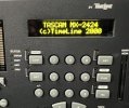
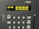
I've been trying to mod my MX2424 with an 20x2 OLED display. Anyone been successful?
I have had luck with other devices, so I was hoping this would be straightforward. I purchased a Newhaven OLED (NHD-0220DZW-AY5 ) from Mouser and soldered on a pair of 7p headers. Swapped out the new display and old, nothing.
When I looked at the pin layout of the Newhaven and the MX2424, I noticed that the pin layout seems to be flipped, so I tried replacing the Tascam 14p ribbon cable with a pair of 7p header jumper cables so I can connect Pin 1 (VDD) on the Tascam to Pin 2 (VDD) on the Newhaven and so on. I get a little intermittent flicker of lines on each character space, but that's it. The only pin that looks like there is a mismatch is Line 5 of the OLED (R/W) and Line 6 of Tascam (NC).
Here are the pin layouts:
Tascam MX2424 (per Front Panel schematic)
Pin No.
1 - VDD - +5 Supply voltage
2 - VSS - Ground
3 - RS
4- NC
5 -EN
6 - NC
7- D1
8 - D0
9 - D3
10 -D2
11 - D5
12 -D4
13 -D7
14 - D6
15- NC
16 - NC
NHD-0220DZW-AY5
Pin No.
1 - VSS - Ground
2 - VDD - Supply Voltage for OLED and logic (+5V)
3 - NC - Must not be connected
4 - RS - MPU- Register select signal. RS=0: Command, RS=1: Data
5 - R/W - Read/Write select signal, R/W=1: Read R/W: =0: Write
6 - E - Operation enable signal. Falling edge triggered.
7 - DB0
8 - DB1
9 - DB2
10 - DB3
11 - DB4
12 - DB5
13 - DB6
14 - DB7
15 - NC - Must not be connected
16 - NC - Must not be connected
Last edited:


