TASCAM 34B No monitoring

MaxWatts

New Member
Joined
Jan 30, 2026
Messages
2
Karma
0
Gear owned
Tascam 34B
I have a Tascam 34B with what was an intermittent and is now seemingly permanent problem. No output, sync repro nor input monitoring.

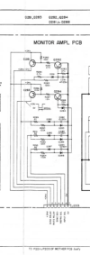
I have recapped the power supply board and the mon amp board. Power supply seems to be delivering the desired voltages to the desired connections. I have reflowed the mother board. I have hiss in the headphone amp but the individual channel volume controls on each track have no influence on the amount of hiss in the phones. This leads me to believe that the headphone amp is working but no signal is flowing to the output section, neither phones nor RCA outs on the back. It is a global problem, not just one channel. There seems to be one component that is preventing all audio signals from reaching the outputs. When it did work, EVERYTHING worked, again, it was not limited to one channel. I am at a loss. Ideas, anyone? I do have the service manual.
 
Some Tascam units used a muting relay that is known to go bad but there is also the chance that some power supply on the cards may have Marcon caps that do not age well- I have had then go bad on the 48 and had to replace them all. There is also a relay that switches between Sync and Repro that goes bad sometimes level wise but usually one mode does work OK. Trace the signals from the RCA jacks on the schematic backwards and if you have a mute transistor near the output then you can unsolder and isolate the collector and see if audio returns. Some mute transistors have shorted on occasion but not that often. Work on Teacs for 50 years I have come across a lot of problems at the factory service and my own service business. Just had a muting problem on a X-3R that was a 220uFd 10V cap reading 5.1 ohms- put a 16V Wurth cap in and all is working again.
 
Hi. Man, am I glad to hear from you. I'll start by telling you what I've done thus far:

I have reflowed the Mother Board.

I have replaced all the electrolytic caps on the Power Supply Board (Nichicon, Panasonic, Wurth, good quality caps).

I recapped the Monitor Amp board as well with quality caps (just the electrolytics).

I jumpered the mute relay on one one of the channel cards to see if that changed anything, it did not.

I do have 6Vdc on the rail that references the coil for the mute relay so normally no trouble there.

I replaced a 1645 transistor on the mute relay circuit on the Power Supply Board, no change.

I replaced the 4 transistors connected to J203 on the Monitor Amp Board.

I do have hiss in the headphone outputs so the headphone amp seems to be working. However, the hiss volume is NOT affected by the individual channel volume controls on the front of the unit which leads me to believe that there is simply no signal passing and is being stymied at one specific point.

This has been an intermittent and global problem. When it works, everything works. When it doesn't, there is no output from any source, repro, sync, nor input.

When it stops working, I get a spike in the levels in my DAW inputs (I'm using the machine to transfer tapes to digital) and then nothing.

I currently have the Mother Board back out of the machine and am rechecking my work as far as the reflowing of solder joints. Since everything seems to flow through the Mother Board, I'm wondering if there is not still a wonky connection there somewhere. I'm being careful as well because the board is not the best quality and it's pretty easy to fry an eyelet.

And, just for the record, Molex connectors suck. My 80-8 was a much better built machine, in my opinion.

One last detail: I live in France so 230-240 VAC coming out of the wall. I'm using a Bronson++ 1000 watt step-down transformer for the 117-120 VAC the machine wants to see. Tape speed is not affected because, if I understand correctly, the 34B uses a DC servo motor so 50Hz or 60Hz is not a problem.

So, this is where I am. I wanted to give you a rundown of what I've tried so far to hopefully avoid going down needless rabbit-holes. Any help, suggestions would be invaluable to me.

Thanks, Dave
 

Attachments

  • J203 Amp.png
    J203 Amp.png
    88.6 KB · Views: 2
OK it is time to stop guessing and just throwing parts at it. This is time to put the unit in source and apply a -10dBV 1KHz sine wave and follow it through the path until it gets to the line out. This is what I would do and have done at Teac service in Chicago. A scope is a required piece of equipment these days. In the 80's you had to may at least $1200 USD to get a good one now with Rigol you can get a 100 or 200MHz scope dual trace and storage for $300-$350 which is peanuts. My last Tek scope that is 300MHz cost me $3600 in 2001. Anyway a sine wave will work it's way through the deck and there are FET called 2SK68 in the circuits to switch what source is routed to the Line out (RCA jack). These sometimes go bad as they are sensitive to voltage spikes or static. I have used a transistor called 2N7000 for these. There were extender cards for the 30 series to help in trouble shooting but they are rare now. Sometimes you have to solder wires on cards to test point on it with the scope. Once you fix the Source signal path then the rest of the system might fall into place or might need it's FETs changed. This is what is needed at this point- using Line in source is best as it does not rely on tape for the signal. I do have tapes with 1KHz recorded on them at 0 Vu so if that is needed sometimes you need to make these on a working machine. Dirty pots can cut signals but that is usually easy to find and spray clean. Make sure the DC voltage is getting to each card on the mother board the bad thing about resoldering these boards is the Plus 15 and Minus 15 Vdc is next to each other and it only take one short to remove all voltages from the cards. It is easy to check with a probe the Pin 8 and Pin 4 of Op amps with the negative probe sticking in a hole in the chassis which is ground it should be +15 at 8 pin and -15Vdc at 4 pin.
 

New threads

Members online

No members online now.