Tascam M-320 is noisy after it warms up

livingtreestudios

New Member
Joined
Jan 5, 2015
Messages
3
Karma
0
Gear owned
m320
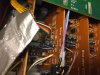
I purchased a mid-1980s M-320 mixer a few months ago for cheap and really like the sound. However, when it warms up after an hour it lets in noise which is most likely of the 60 hertz variety. It hums louder when the AC switches on or I futz with my light dimmer. But like I said, I have zero issues until about an hour after it's been on.

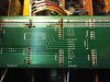
So I began my quest of figuring out what the problem could be. I recapped the power section, the output section, and the 4 channel buss section. The only things not recapped are the 20 input channels and the VU meters. I did, however, change out the lights in the meters and they all work now, however one is dimmer than the others.

The weird thing is if I go direct out from any of the input channels' own output (essentially bypassing the main outs and busses) I get no hum , even hours after being on.

Next up is recapping the VU meters and hope that miraculously solves the issue, but I'm skeptical.

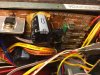
My other worry is that it could be the power transformer. I wouldn't mind swapping that out, but I have no idea how to match it. My electronic knowledge basically boils down to I can replace components fairly well. In fact, I've built my own clone pedals and even a JTM-45 amp clone, but if you ask me how things work, i'd be at a lost most times. I'm a "paint by the numbers guy", I guess.

So my question is: Could it be the power transformer? And if so, how do I find the right replacement? The only Identifying marks are: Teac QL76-504N C55. The Tascam Manual for the M300 series identifies it as: 5320033100

Any help would be great! Thanks, guys
 
As an electronic technician who's been in the business for over forty years, I would be more than happy to "walk through" some step-by-step troubleshooting with you via the telephone, as I'm certain [together] we can solve your problem. Unless it's getting hot... very fast [shorted turns], I doubt there's anything wrong with the transformer. Once fixed, we can post our findings to everyone here on the forum.
 
I have used one of these some time back in a Church. The two things that stand out to me is the light dimmer- if not a DC controlled system the light dimmers usually employ a Triac circuit that produce very sharp section of the sine wave it cuts up for an average voltage result.. The Dimmer of this kind I get away from recording equipment of mixers or tape decks. So Triac controlled dimmers can be quieted by a snubber cap but they are best not used for this application.
The other thing that comes to mind is that the M320 is not a new board so that if 60 Hz hum is working it's way in then it may be that the filter caps in the power supply are affected by heat if surrounding heat sinks as well as their age being somewhat dried out. I would suggest recapping the power supply with a cap size 50% larger than what was in the unit. This not only gives you fresh filtering but also more capacity to fight hum affects. I do this in the power supplies of Teac and Tascam tape decks to make them get back to specs. Using capacitors that are 30 years or older does snot make sense and may result in failures at any point as well as decreased filter to the power supply before any regulators.
Call me technical if you want but I have been working with this stuff a long time as well.
 
DUDES! I have just acquired a Tascam M-312b and am getting NOTHING from it. It looks in great condish and all electrics, VU bulbs, buttons etc seem to work. However, the headphone jack gives off a large hum and I have not been able to provoke any single sign of life. I am running Logic 9 stereo outs into the line in on channels 1&2 and am patching out of Mon L & R into my speakers. Line is pressed on 1&2 and gain is set at 12. Pan is at 12 with L-R pressed. Faders are up. NOTHING. WTF!? Should I go old school and go in the tape returns? Please help. Is the console dead? You would expect at least something no? The master VUs are not moving either.
 
Well I would check for missing accessory jumpers and then forget throwing a lot of signals into it at once do one channel at a time with a sine wave source which can even be from a CD. It seems that from the previous post that these can have power supply issues which will mostly center around old caps. Transformers either work or the unit will be totally dead. If the unit is dead- no lights at all then you need to check the primary of the transformer or a fuse. Your problem might be as simple as a few main out to main in jumpers or accessory jumpers missing. If no channels pass any signal there are probably power supply problems. These are way easier to fix than a Mackie that you would just throw away.
If you are in Chicago I may be able to help.
 
Thank you for the reply and the offer of help :) Before I got too crazy I checked the fuses, as the headphone jack hum implied a PSU problem to me. Sounded like current was coming through the jack. Sooo, I changed the fuses and BANG! It's ALIIIIVVVEEEEE!!! I do have a new question though regarding calibration. The manual makes reference to Channel B: "Assuming you are using a tone generator, set the frequency to 1 kHz and connect the signal to the channel B MIC or LINE INput, whichever is appropriate." I'm not sure what this is referring to....? Thanks again.
 
Most of the calibration has to do with outside adjustment as in getting the unit ready for use. The circuits in the mixer are extremely stable if working correctly and do not change gain amounts by themselves. It has been my experience that most trouble comes from those locations where PA amps that are suppose to plug into speakers are then plugged into mixer input and without any knowledge of what this really does to the mixer amp outputs turned up high is why the damage occurs. Speaker amps expect 8-4 ohm loads. When there is no such load the output voltage goes way outside of the level the mixer can take like plus/minus 30-40 V so it blows out the input amp. This can be a total blow out or a partial damage- this is where gain if it is not right happens. The 1KHz tone can be put in at -10 dBV (about .310 V) and the line input is selected. IF you want to do testing of the Mic in then the right input is in the area of -50dBV. This is when the Trim knob is turned from line to Mic type gains. There could be a difference of 50 to 60 dB in that trim control. I don't recall too many pots in a mixer that allows you to change gain structure. If there were it would be in the Master section for final Buss levels or maybe an Aux send. Most circuits have fixed resistors in them and when there are level problems especially at this age then it is time for a section recap or some new Op Amps.
It is hard to say what you need remotely. This is determined when the mixer is opened and what part is determined to be defective.
 
Too little information is included here. What machine are you using, what is happening when you record 1 K at 0 Vu and then switch to Monitor or tape-does the meter stay at 0? If not the machine is mis calibrated badly. You can test the tape input by taking a jumper out of the buss out and plugging it in. Do not assign the same buss as you are taking the output from as that will be a feedback loop. If the mixer is putting out -10 dBV at 1KHz then the deck if a Tascam should read 0 Vu. The Tascam mixers are set to be used with -10dBV equipment. Does the trim adjustment make any difference in Tape? How about EQ settings
that can cause the levels to be wrong.
 
All ok, thanks again! I have successfully calibrated the old girl. I'm running out of Logic 9 through an Apogee Quartet into the M-312b. Logic's tone generator was set at the wrong db. Learning is fun!
 
FYI, I fixed my board as well. I recapped the power supply first and still had noise. I also recapped the mains, the aux, and the busses. I still had noise. So I finally changed out the 2 bridge rectifiers in the power supply and problem solved. Now the board sounds great. I never calibrated it though. For some reason I didn't think I needed to do this if I'm not recording to tape. Do these boards need to be calibrated? Mine seems to be working just fine. But I'll go the extra mile to make this board sound great if I have to.
 
It sounds like you are doing well in fixing this thing. How did the Bridge rectifiers have noise causing condition? Do you mean to say that one of the diodes in the bridge was open or shorted?
In a case like that I would upgrade the Amp side of the bridge to the next bigger size. Like 1.5A to 4 A size. These parts can be had almost anywhere. When I had the M320 I never had a spec of trouble from it but I bought it from the Employee sale for a Church. The Musician in the Church were trouble though- the management as usual not the players- they were great and I made a number of demo tapes with them and some of the songs were put on FM radio shows. I did radio production for the Church for 7 years.
 
My best guess is that one of the bridge diodes was bad and AC current was leaking into the unit producing noise. Like I earlier said, the noise wasn't right away, it built up slowly as the unit built up. I found the parts fairly easy and cheap.
 
Your problem may be due the the power transformer that you are discussing. Most of the times these transformers make interference with the audio signal. If you have other inductors in your circuit, watch them also. If they are adjustable then try to adjust them. Maybe your problem get fixed.
 
Hey everyone, I'm new the forum but I have a question about my Tascam M320.

The sub mix section has been giving me problems. Sub mix 2 rarely works on most channels and sub mix three works only on a few channels. Both are intermittent though, I think the mixer is set up so that each channel is an individual strip, my question is does this seem like a problem with each individual channel strip or a problem with the caps in the sub mix section? My friend is a electrical engineer but has not worked on too many mixers so I was hoping to try and narrow it down for him to work on it. Thanks in advance!
 
The place you start is with service manual and block diagrams. I am thinking the sub mix you are referring to is Aux 2. If not then you need to use the correct terms as expressed in the manual for all to have their thinking on common ground. The Aux send path does not have all that much in it. I would start by putting in a line sine wave and then finding out why it does not get to the Aux 2 Master or the problem might be as simple as some buss bridges along the cards needing exercise or some Deoxit sprayed on them. People that are EE don't necessarily qualify for good repairmen- it depend on if they have a good technical back ground as well. I had a Nasa Engineer who has to be smarter than me but I had to fix his tape deck. Different people for different things. There can be dirty pre/ post switches or even an intermittent pot at the master. All these are due to be sprayed with Fader Lub or Deoxit.
If you look at the mechanical drawings of the unit there are a number of interconnecting buss PCB on the bottom. These may need reseating or some movement. The bottom plate of the mixer need to come off. Care must be exercised if the unit is to me laid on it's face- I would advise some pieces of wood be set up so as to support the mixer by it's outer frame.
 
I'm sorry for the confusion, as far as terminology I thought I was using proper terms. I was not referring to the aux sends, although my aux send 1 does not pass sound at all, a problem I'd like fixed as well. What I was referring to in my previous post is the program busses available on each channel to route the signal to program buss 1 2 3 or 4. Program buss 2 and 3 work intermittently on every channel, so I was wondering if it's something I need to check on each individual channel strip. Also to clarify my friend is a repair tech at the Macintosh Amp factory, he has worked on microphones and pedals and tape delay units. He has plenty of experience and definitely has the knowledge necessary to address the problems I'm having I was just hoping to narrow it down for him. Again sorry for the confusion any help is greatly appreciated, I'm trying to get this mixer fixed up so I can start running sessions with it. Thanks!
 
OK, Mixers have so many points the signal can be interrupted at it is hard for anyone to tell where to start to look for a problem. If I knew where it was I would probably would be working on it. One thing that has the definite possibility besides individual switches and pots is the pcb's across the bottom of the mixer which act as buss lines to the final master section. Since you seem to have multiple lines of failure this is where I would start. I owned one of these for a time back in the 80's however being it was new there were never a problem with it. It is a matter of your friend to go through and check all the functions and make appropriate corrections as he goes.
This is not going to be a 20 minute repair but depending on what e finds it might come back o life pretty much. One of the major mistakes people make when having these mixers is smoking in their presence and not covering them over when not in use. This when done promotes switch failures and pots that are noisy. Of course a lot of the problems can be resolved with spray from Deoxit which is on sale for $9.00 a can until a time in January. You might want to get a couple of cans. It can be used on switches and pots of tape decks as well. I use it all the time.

As an additional precaution or to save time, you might want to look at the service manual and order some spares such as the NJM Op Amps and some common transistors to have on hand.
Then when the unit is worked on the person will have the parts and there will not be a wait for the parts. One Input section uses NJM5532D and some NJM2041DD and other parts are NJM072DE. The NJM5532D can be replaced by NE5532 type amps and the NJM072DE is like or equivalent to TLO72 types. The NJM or JRC2041 is a low noise op amp 7MHz GBW and 3V/uS slew rate- think they are still available. It is best to place sockets in where chip need to be replaced. The Best sockets are Machine pin gold from Unicorn Electronics in he state PA.
 
Last edited:
So I opened up the M320 today to take a look, I took some photos and thought id post them for anyone who would like to see the progress. I took some pictures of things that are noticeably wrong, at least to me. Like the leaking caps in the power supply section. Some corroded solder joints, the one that is also eye catching is the set of cables coming off of the aux PCB that are just taped off with duct tape. Possibly causing the Aux 1 no signal problem. My friend will start going through it soon, hopefully he can find the problem with my program busses and aux send 1.
 

Attachments

  • image.jpg
    image.jpg
    95.8 KB · Views: 21
  • image.jpg
    image.jpg
    122.2 KB · Views: 20
  • image.jpg
    image.jpg
    131.4 KB · Views: 18
OK, I have to straighten a lot of assumptions out here. The tape you show is not Duck tape but most likely a shielding tape. the Leaking on the power supply caps has been there from day 1 and it is not leaking but any Technician who has worked on anything in the last 20 years will tell you it is that glue that was required by the FTC for some goofy reason and it was probably a kickback. The glue has been in all products and it gets dried out and becomes conductive with humidity so that it needs to be removed. New fresh Electrolytic caps- often times 50% higher in value are installed when this is done. Why 50% higher? Because these units are designed well and then modified by the penny pinchers. The 2200uFd cap gets reduced to 1000uFd as the unit only has to last the 90 days for warranty. The original part should be put in because that is how it was designed. Remember that no one knows what that value is because we have no access to the original design but I have had no trouble putting in 50% or 100% larger capacity value in. It is also common for the caps to be 1/2 to 1/3 the size of what they were in old technology. I am talking the cap value not the voltage. If the caps is 50 volts it still is 50 volts.
Soldering- the electronics from Japan across all brands is pretty sub standard. They use a wave solder method to make boards. Almost all things need a competent technician to resolder (add) solder to the weak joints that are there. If you see circles around the leads of components then they are either soldered poorly or may have cracked from thermal cycling. I often times resolder 100 to 200 joints in tape decks made by the same people. This is not aerospace grade manufacturing! I worked at Hughes at one time and have had Nasa Soldering training at another job. The tape if having a metallic layer on it is the shielding. I have never known any manufactured in 45 years to put Duck (grey or brown) cloth tape in a unit. This if it is done comes from a slip-shot repair guy.
I have worked at Sony and Bigston as well as Teac and was manager of a Customer Service section of a larger company with regard to refurbishing and repair of all Electronics brands. You would be surprised at who they let work on the equipment. The only way you get something fixed right is from a good technician- despite all the TV commercials I see, DeVry does not put out the best product in Technicians and sometimes lets those out simply because the paid the $10,000 and do not know what they are doing. I had one guy spend 5 hours on a boom box. I was a supervisor at the time and asked him what was wrong- he said no voltage. I asked him if he ohmed out the transformer primary and he said yes- what did you get I asked. He said it was open. I said SO? He still did not know what to do. What school did you come from? DeVry!
Not everyone is like that but this guy should have never gotten out of the gate.
 

New posts

New threads

Staff online

Members online