Tascam 38 op-amps

edthebear

New Member
Joined
Feb 11, 2013
Messages
11
Karma
0
Gear owned
Tascam 38
Hello everybody,
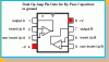
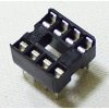
Can anybody tell me how I identify the opamps on the play/rec pcb on the Tascam 38. I struggle with the sybols etc in the circuit diagrams. I read an article on ugrading the opamps on that board to LME497020's or AD8599's so I need to identify them. My guess that they are the dip chips but I cant be sure which ones if I am right. Can you help me?
 
The opamp is at U101.

If you are looking at the card with the with the white plastic M-B plugs towards you it is on the right side just behind the input transformer.

You want to be careful with opamp replacements, because you can cause circuit oscillations that will end up offering overall performance well below the OEM.

The opamp you mentioned is a good one but needs (at minimum) by-pass caps to prevent the oscillations. It also takes a bit more power than the OEM opamp and might compromise the power supply.

An easy replacement that does not complicate performance but which can greatly improve audio performance is the TL072. It has good frequency response, is very inexpensive (under $1.00), and abundantly available.

I'd recommend putting in a socket after removal of the 4558 at U101. In this manner you can then swap out opamps w/o damaging the circuit board with multiple soldering.

If you are new to this be careful. You might want to tag onto someone a bit more experienced especially if you are not experienced with soldering.

Just hollar if anything else.

I had forgotten to add that the OPA 2604 would be a better choice for a higher performing opamp but you should use by-pass caps like a .01 mfd 63V WIMA film cap from each power rail pin to ground.

You can experiment with the TL072 and then go to the OPA2604 later.
 
Oh thank you so very much for your detailed response! If I may I may want to come back to you on the by-pass issue if that's OK. My soldering skills are quite good but my knowledge of what purpose components have and indentify them in ciruit diagrams is poor. My father was expert at it but was quite secretive about is knowledge. Not that I can really blame him with me being almost 64 and trying to learn new tricks!
Thanks again!
Eddie
 
when you look at drawings in Tascam's manuals understand that they are showing the "foil" side of the board with the outlines of the component placement. It can get confusing.

Fooling with this equipment is something most of us have been doing since very young. It is an addiction.

I like getting more out of what's there and tend to go quite nuts with upgrades.

As to soldering a 15 watt iron is what you need and a solder sucker tool.

I don't know where you are located, but if you can get a Radio Shack #64-2051B soldering iron it will help keep the heat down on the boards. It is around $8.00, and the replacement tips are only $3.00 each.

As to opamps it is sometimes a trial and error basis as the higher grade units can oscillate and produce noise due to their greater capabilities and more complex construction. Think of them as high maintenance women!

I alway start with basics. I first completely rebuild the power supply with higher grade and higher volatge caps, and then by-pass all the large caps with .01 mdf WIMA's.

I will even replace all the caps on the sound cards with very high grade "audio series" caps and in some cases replace the input caps with high grade film caps to smooth the audio signal.

Take your time and get to this all slowly.
 
Thanks once again for your follow up. I have a lot to take in don't I. I will certainly act on your advice and take it slow.
Ed
 
That is the best way

Remember that there are many very knowledgeable persons who can help.

I have been at this for many, many yeears and feel I have learned more in the past 2 years then all those before!

Help is always just a request away.

I have attached an 8 pin diagram for op-amp bypass caps to ground. #4 & #8 (red marks) are those outputs used to run .01 caps to ground to rid the oscillations of the higher grade op-amps
 

Attachments

  • Op-amp Mod Diagram.GIF
    Op-amp Mod Diagram.GIF
    8.3 KB · Views: 42
Hi again,
Can I just double check with you on a couple of things:
1. If I fit the TL072 I will not have to use by-pass caps?
2. When you say about fitting a socket. Is that a SOIC to DIP adaptor?
Thanks for your time and the diagram.
Ed :p
 
Thanks, that's great. By the way. You asked where I was based. I live in Mid-West Wales UK. Nothing here but sheep, rain and some very nice people. Certainly no Radio Shack!
Ed
 

New threads

Members online