Morning Everyone,
Haven't been here for a while even though I've been a member since 2014. My DM4800 has been performing well over the last 13 years although I did have to replace the LCD menu screen like many here. You guys were invaluable for doing that of which I was greatly appreciative!!
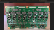
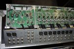
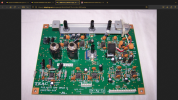
The problem I'm having now is with the 48v phantom power supply. It has failed across all channels. I was experiencing a "pop" of sorts through input #16 where I have my Polytone guitar amp mic'ed (AKG C414) and set up with Comp, EQ, effects etc.........At first I thought it was the house electrical system just fluctuating and causing my amp to litely pop every now and then. I do have my entire recording setup on a battery backup in case of electrical failure so I can get everything shutdown in an orderly manner if that happens but the amp isn't on it. I checked the amp, mic cable, mic, phantom power switch, trim pot etc.... I checked everything I could think of. The problem was intermittent and would go away for a while. The other day I sat down to play at bit while I watch my financial shows and the phantom power was completely gone. Nothing. Took the 414 and plugged it into the other inputs and pp to no avail. Plugged a dynamic mic in and the channel inputs all work fine so I'm at a loss here. To get an idea of what I could possibly be looking at I found a PCB board on eBay that appears to be one of the 3 boards making up the input section. I only recognized it because of the switch configuration with 2 phantom power switches for the 8 inputs. I've included a picture for reference. Looks like it would be pretty straight forward to replace. If the problem originates in the board. But, I'm thinking that if it was just one board that all 3 boards wouldn't go out at once so this leads me to believe the problem is upstream from the PCB boards. Is there a central thingamajig that is the main 48v power that provides the power to which ever input and pp switch is activated? I don't know.
Has anyone here had a problem with the phantom power on your 3200 or 4800? I can work around this problem with Presonus EUREKA preamp I have as it has 48v power, EQ, Comp and I can just run it into the line input of the 4800 but, I would prefer to use the input of the 4800 itself. I sure would appreciate some help from you guys that pop the hood on these things and are knowledgeable of what your looking at. If anyone can shed some light on this for me I would greatly appreciate the help. I love this board as it is the center of my recording setup and come hell or high water, I'm gonna fix it, have it fixed or something. Here is a picture of the board.
Thanks in advance fellas for any help you can afford me!!
DaveDC9
Haven't been here for a while even though I've been a member since 2014. My DM4800 has been performing well over the last 13 years although I did have to replace the LCD menu screen like many here. You guys were invaluable for doing that of which I was greatly appreciative!!
The problem I'm having now is with the 48v phantom power supply. It has failed across all channels. I was experiencing a "pop" of sorts through input #16 where I have my Polytone guitar amp mic'ed (AKG C414) and set up with Comp, EQ, effects etc.........At first I thought it was the house electrical system just fluctuating and causing my amp to litely pop every now and then. I do have my entire recording setup on a battery backup in case of electrical failure so I can get everything shutdown in an orderly manner if that happens but the amp isn't on it. I checked the amp, mic cable, mic, phantom power switch, trim pot etc.... I checked everything I could think of. The problem was intermittent and would go away for a while. The other day I sat down to play at bit while I watch my financial shows and the phantom power was completely gone. Nothing. Took the 414 and plugged it into the other inputs and pp to no avail. Plugged a dynamic mic in and the channel inputs all work fine so I'm at a loss here. To get an idea of what I could possibly be looking at I found a PCB board on eBay that appears to be one of the 3 boards making up the input section. I only recognized it because of the switch configuration with 2 phantom power switches for the 8 inputs. I've included a picture for reference. Looks like it would be pretty straight forward to replace. If the problem originates in the board. But, I'm thinking that if it was just one board that all 3 boards wouldn't go out at once so this leads me to believe the problem is upstream from the PCB boards. Is there a central thingamajig that is the main 48v power that provides the power to which ever input and pp switch is activated? I don't know.
Has anyone here had a problem with the phantom power on your 3200 or 4800? I can work around this problem with Presonus EUREKA preamp I have as it has 48v power, EQ, Comp and I can just run it into the line input of the 4800 but, I would prefer to use the input of the 4800 itself. I sure would appreciate some help from you guys that pop the hood on these things and are knowledgeable of what your looking at. If anyone can shed some light on this for me I would greatly appreciate the help. I love this board as it is the center of my recording setup and come hell or high water, I'm gonna fix it, have it fixed or something. Here is a picture of the board.
Thanks in advance fellas for any help you can afford me!!
DaveDC9